A Practical Guide to Camera and Composition in 3D
Follow an illustrative armchair project to learn how to choose focal lengths, camera heights, depth of field and aspect ratios that make 3D renders look real.
 Imogen Clarke

Camera and composition in 3D is the work of choosing a focal length, a camera position, a height and a frame inside a virtual scene. It looks like the easy part of a render. The model is built, the materials are approved, the lights are placed, and all that is left is to point a camera at the result. In practice, it is where a great many renders quietly fail, because a virtual camera has none of the physical limits of a real one. It can sit inside a wall, use a 9mm lens on a product shot, and move along any path, at any speed, with no rig underneath it.
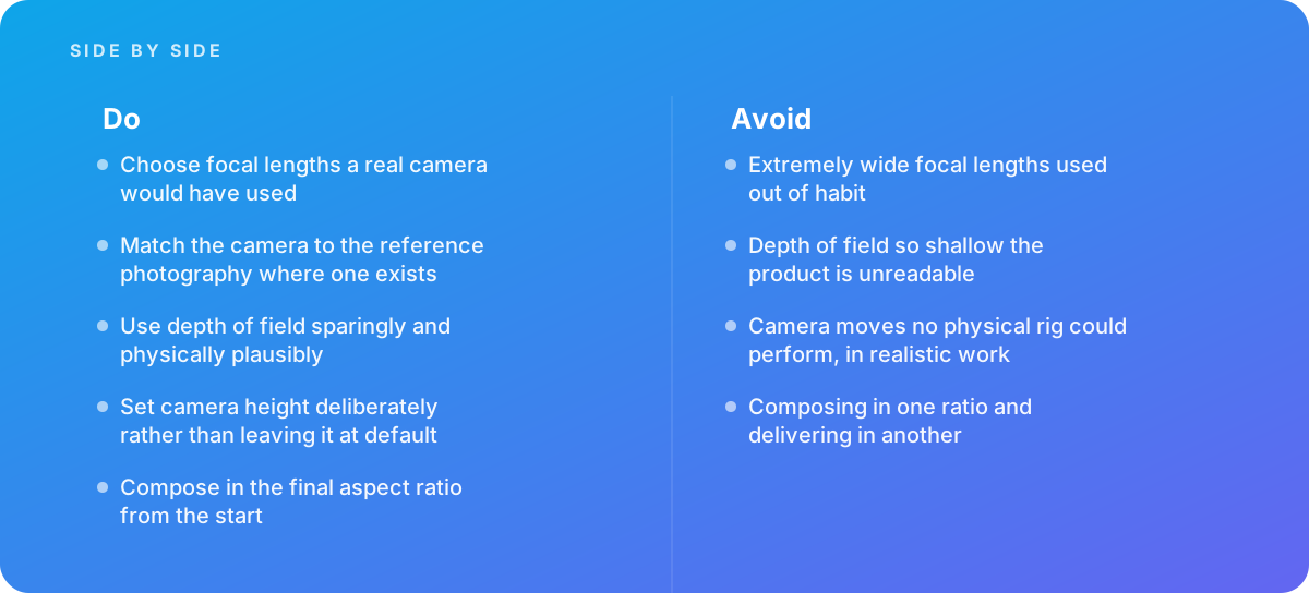
That freedom is the problem. The physical limits of photography are also what make photographs read as real. Viewers have spent their whole lives looking at images taken with real lenses from real heights, and they notice, often without being able to say why, when a render breaks those habits. A product shot through an extremely wide lens, a blur so shallow the product is unreadable, or a camera sweep no crane could perform all make an image feel synthetic, however good the materials are.
This guide follows one illustrative project from brief to delivery and explains each camera decision along the way: why a focal length was chosen, where the camera sat, how depth of field was set, and how the team avoided the traps that catch most 3D teams. The project is a composite example written for teaching. It is not a client story, and its numbers are illustrative. It is written for marketers and brand owners who commission renders and for artists who set up the cameras.
The Illustrative Brief: An Armchair Range That Had to Sit Beside Photography
Here is the setup. A furniture brand is launching a range of twelve upholstered armchairs: one frame in six fabrics and two leg finishes. The brand already has a photographer's lifestyle shoot of the hero chair in a real living room. It wants CGI for everything else, because photographing twelve physical samples in four crops is slow and expensive, and several fabrics will not be manufactured in time for the launch.
The deliverables were typical of an e-commerce and social launch. Each variant needed a front three-quarter hero, a straight side profile and a detail crop of the arm and seam. Each still had to be delivered in four aspect ratios: 1:1 for marketplace listings, 4:5 for social feeds, 16:9 for the website hero banner and 9:16 for stories. The brief also asked for one short turntable-style motion clip of the hero chair, and for the CGI hero chair to be composited into two of the photographer's real room plates, so that the CGI and the photography would appear side by side on the same product page.
That last requirement shaped every camera decision. If CGI sits next to photography on the same page, the viewer compares them directly. Any mismatch in perspective, camera height or depth of field shows up immediately. So the project's working rule was simple: every virtual camera had to be one a real photographer could have used on that shoot.
- Week 1 Brief review, collection of the photographer's reference files and camera data, and a written camera plan covering focal lengths, heights and aspect ratios.
- Week 2 Sensor and lens setup, camera match to the two lifestyle plates, and first grayscale composition tests in all four ratios.
- Week 3 Hero variant lookdev, depth-of-field tests and approval of three locked camera setups.
- Week 4 Batch rendering of all twelve variants through the locked cameras, then automated and manual QA.
- Week 5 Motion clip, plate composites, final crops and delivery with a camera specification sheet.
Five weeks is a reasonable illustrative schedule for a range of this size, not a benchmark. The camera work itself took a small share of the hours, but it came first. Changing a camera after lookdev and batch rendering means re-rendering everything that came through it.
Reading the Reference Photography Before Touching the Camera
The first task was not in the 3D application at all. It was an audit of the photography the CGI had to match. When renders must sit next to real photos, the real camera is the specification. The team collected three things from the photographer: the raw files with their metadata, the camera body model, and notes from the set.
What the metadata tells you, and what it does not
Image metadata usually records the focal length, aperture, shutter speed and camera body. The body matters because it tells you the sensor size, and focal length means nothing without it: a 50mm lens on a full-frame sensor frames a very different scene from a 50mm lens on an APS-C body. In this example, the photographer shot on a full-frame body, which has a sensor of roughly 36 x 24 mm. The lifestyle plates were taken at 50mm and f/5.6, and the detail shots at 100mm.
Metadata does not record camera height or distance, and those are exactly what a plate match needs. So the team asked the photographer, who had written down the tripod height for the room shots: the lens center was about 1.1 m above the floor, roughly the eye line of a seated adult. For the second plate, where the notes were missing, the height had to be worked out from the image, using the horizon line and known dimensions in the room, as described later.
Reading the look, not just the numbers
Beyond the numbers, the team noted the look of the photography. Verticals were kept straight, so the photographer had leveled the camera rather than tilting it down. The background fell off gently but stayed legible. The chair was framed with generous space above, in line with the brand's layouts. Each of these observations became a camera rule for the CGI.
Decision: The team wrote a one-page camera plan before any 3D camera existed. It listed the sensor size, the approved focal lengths (50mm for scenes, 70mm for heroes, 100mm for details), the camera heights for each shot type, the aperture range and the four delivery ratios. Every later camera was checked against this page, which stopped the gradual drift that happens when each artist frames shots by eye.
Setting Up the Virtual Camera: Sensor Size and Focal Length
Virtual cameras are configured against a sensor size, just like real ones. In Blender, the default camera uses a 50mm focal length on a 36mm-wide sensor. The Blender camera documentation explains how focal length, sensor size and sensor fit together set the field of view. Offline renderers such as RenderMan expose the same physical parameters, and the RenderMan camera and lens documentation is a good reference for how focal length, f-stop and focus distance map onto the simulated optics. The first practical step was to set every camera in the scene to a 36 x 24 mm sensor, matching the photographer's full-frame body, so that "50mm" in the render meant exactly what it meant on set.
Why focal length is a perspective decision
Focal length determines perspective compression, exactly as in photography. To keep a subject the same size in frame, a wider lens forces the camera closer and a longer lens forces it further back. Distance is what changes how near and far parts of the subject relate to each other: close cameras exaggerate the parts nearest the lens, and distant cameras flatten them. For the armchair, that choice was visible. At 35mm the camera had to sit about 2 m from the chair to fill the frame, and the front arm looked swollen compared with the back. At 70mm the same framing needed about 4 m, and the proportions matched what a shopper would see across a showroom.
| Focal length (full frame) | Horizontal field of view | Typical real-world use | Use in this project |
|---|---|---|---|
| 24mm | About 74 degrees | Interiors, tight spaces | Rejected for product; exaggerates the nearest arm |
| 35mm | About 54 degrees | Environmental and wider room shots | Tested, rejected for heroes |
| 50mm | About 40 degrees | Natural room views, lifestyle scenes | Room plates and scene renders |
| 70mm | About 29 degrees | Product heroes, furniture catalogs | Front three-quarter hero and side profile |
| 100mm | About 20 degrees | Details, texture and stitching | Arm and seam detail crops |
The field-of-view figures follow from the standard relationship between sensor width and focal length (twice the arctangent of half the sensor width divided by the focal length). You do not need to calculate them by hand, but it helps to know that "wide" and "long" are about angle, and that angle only means something once the sensor is fixed.
The habit of the wide lens
Extremely wide focal lengths are among the most common camera mistakes in 3D, and they usually come from habit rather than choice. In a viewport, a wide lens is convenient because you can see the whole scene without backing the camera through a wall. Artists often frame the final shot at whatever focal length they were navigating with. The result is a product that looks subtly stretched and bulbous, with every near surface exaggerated. A real product photographer would rarely use anything under about 50mm for a hero shot of a chair-sized object. That is the range to start from, not the one to arrive at by accident.
Camera Height: Where a Chair Is Seen From
Camera height strongly affects how a subject reads, and it is the setting most often left at whatever the scene template provided. For a chair, height changes what the viewer understands about the product. A camera at standing eye height, around 1.5 to 1.6 m, looks down into the seat, which shows off the cushion but makes the chair look small and low. A camera near seat height, around 0.45 m, makes it look imposing and hides the seat. A camera around the top of the arms shows the chair's proportions most honestly.
The heights the team chose
The illustrative project used three heights. For the front three-quarter hero, the lens center sat at 0.9 m, a little above the arm tops, so the seat depth was readable without looking down on the product. For the side profile, the camera sat at 0.55 m, close to the seat cushion, so the arm, back and leg angles read as a clean silhouette. For the room scenes, the camera matched the photographer's 1.1 m tripod height exactly, because those renders had to sit beside the plates.
Keeping verticals straight with lens shift
Once the camera is lower than the top of the subject, or higher than its base, there is a temptation to tilt it to center the product. Tilting makes vertical lines converge: chair legs lean inward and room walls lean outward. Architectural and furniture photographers avoid this with shift lenses or by correcting perspective afterward. Virtual cameras make it easy. In Blender the camera has shift controls, and most renderers offer an equivalent. The team kept every camera perfectly level and used vertical shift to move the frame up or down, which kept the legs straight and matched the look of the photography.
A level camera with shift is also easier to reproduce across a range. A tilt angle is one more number to copy exactly, and small differences in tilt between variants show up as leg angles that disagree from one product image to the next.
Composing in the Final Aspect Ratios From Day One
Composing in one ratio and delivering in another is one of the most expensive camera mistakes because it is found late, often by a social media manager trying to crop a 16:9 hero into a 9:16 story and finding the chair's legs and the top of its back cut off. The fix is to decide the delivery ratios before the first composition test and to build cameras for them.
One camera per ratio, or one oversized master?
There are two common approaches. The first renders one large master frame and crops every ratio from it. That is efficient, but it forces a compromise: a composition that works in both 16:9 and 9:16 has so much empty space that neither crop is strong. The second builds a dedicated camera for each ratio, sharing the same focal length and height but with its own distance and shift, so each frame is composed on purpose.
The illustrative project used both. For the side profile and detail shots, where the subject is compact and centered, one master frame at 1:1 with generous margins cropped cleanly to 4:5 and 16:9. For the hero, the team built dedicated cameras for 16:9 and 9:16, because a landscape banner needs the chair offset to leave room for headline text, while a vertical story needs the chair lower in frame with space above for interface elements. Four renders per hero cost more render time but removed any need to reshoot later.
Safe areas and text space
Composition for marketing is not only about the product. The website banner reserved the left 40% of the frame for copy, so the chair sat on the right third. The 9:16 story frames kept the top and bottom bands clear of anything important, because platform interfaces cover them. The team loaded these safe-area guides into the camera views as overlays from the first grayscale test, rather than checking against them at the end.
Trap avoided: In Blender, a camera's sensor fit set to Auto applies the sensor width to whichever image dimension is larger. When a render is switched from landscape to portrait, the 36mm is suddenly applied to the height, and the field of view changes even though the focal length has not. The team set the sensor fit to Horizontal on every camera and documented it, so a 70mm lens meant the same horizontal coverage in every ratio.
Depth of Field: Physically Plausible, Used Sparingly
Depth of field is simulated in 3D, and it is easy to overdo. A physical lens has a set of limits: a given focal length, aperture and focus distance produce a specific zone of acceptable sharpness, and a photographer who wants a shallower look has to trade something for it. A virtual lens has no such limits. An artist can dial in an f/0.5 blur, or set the focus distance on empty space. The result is an image where the front of the product is sharp and the back is mush, which reads as either a miniature or a mistake.
Worked example: how much of the chair is actually sharp
The team calculated the depth of field before rendering rather than judging it on screen. The chair in this example is about 0.85 m deep. The hero camera uses a 70mm lens focused at 4 m on the front of the seat. Using the conventional circle of confusion for a full-frame sensor (0.03 mm), the zone of acceptable sharpness works out approximately as follows.
| Aperture | Near limit | Far limit | Total depth of field | Result for a 0.85 m deep chair |
|---|---|---|---|---|
| f/1.4 | About 3.87 m | About 4.14 m | About 0.27 m | Only the front of the seat is sharp; unreadable |
| f/2.8 | About 3.75 m | About 4.29 m | About 0.54 m | Back legs and rear frame soft |
| f/5.6 | About 3.53 m | About 4.62 m | About 1.10 m | Whole chair sharp; background softens gently |
| f/8 | About 3.35 m | About 4.95 m | About 1.60 m | Whole chair sharp; background only slightly soft |
The figures are calculated values for this illustrative setup, not measurements, but the lesson carries over. At f/2.8, a setting many artists treat as moderate, a chair-sized product is not fully sharp at this distance. The team chose f/5.6 for the hero and f/8 for the side profile, because the silhouette had to be crisp from the front leg to the back. Focus was placed about a third of the way into the chair rather than at its front edge, because depth of field extends further behind the focus point than in front of it.
Keeping focus behavior consistent
The optics behind depth of field are the same ones photography has used for decades. Standards bodies such as ISO, which publishes standards for photographic optics, codify the terminology and measurement conventions lenses are specified against. For a 3D team the practical point is narrower: pick a real f-stop, a real focus distance and a sensor size, and let the renderer compute the blur, rather than adjusting a blur slider until it looks right. Physical values keep depth of field consistent from shot to shot, and they make it possible to match the photographer's f/5.6 plates exactly.
There is a production reason as well. In-render depth of field adds noise that needs more samples to clean up, and a post-process blur driven by a depth pass can fringe around fine edges like fabric fuzz and chair legs. The team rendered hero depth of field in-camera and kept a depth pass for small adjustments only. If you are pushing high sample counts on complex scenes, it is worth reading about GPU memory limits in rendering before committing to heavy in-camera effects across a large batch.
Matching the Camera to the Lifestyle Plates
Matching plates requires the real camera's focal length and height. For the first room plate, the team had both: 50mm on a full-frame body, lens center at 1.1 m. They set the virtual camera to those values, placed it at the recorded distance from a known feature in the room (the edge of a rug that had been measured on set), and adjusted pan and roll until the room's lines matched the photograph. Because two of the key values were fixed, only rotation and a small positional adjustment were left, and the match took under an hour.
When the notes are missing
For the second plate the tripod height was not recorded. The team worked it out from the image. The horizon line of a level camera sits at the height of the lens, so any object in the room that the horizon line cuts gives a height reference. A door frame of known height and a sideboard of known dimensions gave two independent estimates, which agreed at roughly 1.05 m. With the focal length from the metadata and the height estimated, the team used a perspective-matching tool to solve camera rotation from the vanishing lines of the floor and walls, then checked the solve by placing a simple box the size of the real sideboard and confirming it lined up with the photo.
A camera match is also the basis of related techniques. If you need to project the photograph itself back onto rough geometry, for example to add parallax to a still, the principles overlap heavily with camera projection mapping. The same measurement discipline also applies when the "plate" is a live background on an LED wall, which is covered in our guide to virtual production and LED volumes.
Lens distortion and the last few pixels
Real lenses distort slightly, and a render from a perfect virtual lens will not line up with the edges of a real plate. At 50mm on a quality lens the distortion is small, but it becomes visible where straight lines in the room run near the frame edges. The team rendered with a little overscan and applied a distortion profile matched to the plate in compositing, rather than trying to reproduce the distortion in the render camera. They also added matching grain and a slight chromatic softness at the corners, so the CGI chair did not look cleaner than the real room around it.
- Sensor size set to the real camera body, with sensor fit fixed to one axis.
- Focal length taken from the plate metadata, not estimated by eye.
- Camera height measured on set or solved from the horizon line and known objects.
- Camera kept level with shift used for framing, matching the photographer's straight verticals.
- Aperture and focus distance matched to the plate, so the background falloff agrees.
- Lens distortion, grain and edge softness matched in compositing.
- A proxy object of known size placed to verify the solve before final rendering.
The Motion Pass: Camera Moves a Real Rig Could Perform
The brief included a short motion clip of the hero chair. This is where the freedom of a virtual camera does the most damage in realistic work. A virtual camera can accelerate instantly, fly through a gap narrower than a lens, orbit at constant speed with no ramp, and change height and focal length together in ways no dolly, slider or crane could manage. Viewers read these moves as computer-generated, even if the chair itself is photoreal.
Designing the move against a real rig
The team designed the clip as if it would be shot on a motorized slider and turntable, which is a common real-world setup for furniture product video. The chair rotated 60 degrees on a virtual turntable over eight seconds, while the camera made a slow lateral slide of about 1 m at a constant height of 0.9 m. Both moves used ease-in and ease-out curves, because physical motors ramp up and down. The focal length stayed fixed at 70mm. Focus tracked a point at the chair's center, and focus changes were kept slow enough for a human focus puller to have managed them.
A useful test is to describe the move in words a camera operator would understand: "slider left to right, a meter over eight seconds, chair turning on a lazy Susan." If a move cannot be described in those terms, it probably should not be in a realistic product film. Stylized and motion-graphics work can break these rules on purpose. Realistic work that sits next to photography should not.
Frame rate and motion blur
The clip was rendered at 24 frames per second with motion blur equivalent to a 180-degree shutter, meaning an exposure of about half the frame interval. That matches the look most viewers associate with filmed video. A renderer with motion blur disabled produces a crisp, stuttering movement that looks like a game engine capture. With the slow move in this example the blur was subtle, but it was there, and it helped.
Whether a clip like this is rendered offline or in a real-time engine is its own decision, with trade-offs in lighting accuracy, iteration speed and cost. Our guide to choosing real-time or offline rendering covers that choice in detail. For this project, offline rendering was chosen so that the motion clip would match the stills exactly.
Locking One Camera Treatment Across Twelve Variants
A range needs consistent camera treatment. When shoppers scroll a category page, they compare products tile by tile. If one chair was framed from 0.9 m at 70mm and the next from 1.0 m at 60mm, the second chair looks different in size and shape even though the frame is identical. Consistency is not a style choice here. It is what makes the product comparison honest.
How the cameras were locked
Once the hero variant was approved, the team locked the three approved cameras: position, rotation, focal length, sensor, shift, aperture and focus distance, for every ratio. The cameras lived in a separate linked scene file, so the variant scenes referenced them instead of each holding its own copy. Swapping fabrics and leg finishes happened on the chair asset alone. No one opened a camera to adjust it for an individual variant. If a variant looked wrong through a locked camera, that was treated as a material or lighting issue to fix, not a reason to reframe.
That discipline depends on a pipeline built for variants. The mechanics of driving one scene through many material and model combinations are covered in how to get batch rendering variants right, and keeping a locked camera file from being edited by accident is much easier with the practices in version control for 3D assets. In this project, the camera file was tagged at approval, and every final render recorded which camera version produced it.
Automated checks that caught drift
Before final renders, a short script compared each variant's camera settings with the locked specification and flagged any difference. It caught one real problem: a variant file that had been opened with a local camera override left over from a test, at 65mm instead of 70mm. The difference was invisible in a single image but obvious once that tile sat in a grid of twelve.
Decision: The detail crops at 100mm were framed on a fixed point on the chair frame, the front seam where arm meets seat, rather than on the fabric pattern. Fabrics with large patterns might otherwise have pulled each detail shot toward whatever motif looked best. Anchoring the frame to the geometry kept every detail crop comparable, which is what the product page needed.
Review and Delivery: How the Camera Work Was Checked
Camera problems are easier to catch in a structured review than in a general look at a render. The team reviewed each approved camera at three levels.
In isolation
Each render was checked for sharpness across the full depth of the product, straight verticals, correct space above and below the chair, and clean safe areas for the ratio. Reviewers looked at the renders at 100% zoom and at the size they would appear on a phone. Depth-of-field problems show at full size, and composition problems show small.
In context
The heroes and profiles were placed into mock-ups of the actual product page, social post and banner templates, with real copy. This is where a frame that looked fine alone turned out to put the chair's back under the headline in the 16:9 banner, which led to a small shift adjustment before the camera was locked. It is much cheaper to find that during approval than after 144 renders.
Next to the photography
The composited room plates were checked side by side with the untouched photographs from the same shoot. The review focused on perspective (did the chair's legs converge like the sideboard's?), height (did the eye look at the seat from the same angle as the real furniture?), and falloff (did the background blur the same way?). One composite was sent back because the chair's shadow contact was fine but its depth of field was slightly crisper than the rug beside it; the focus distance had been set to the chair rather than to the photographer's focus point in the plate.
The delivery package included the renders and a one-page camera specification sheet: sensor, focal lengths, heights, distances, shift values, apertures, focus distances and ratios for each shot type. That sheet is what lets a future product added to the range, perhaps a matching footstool, be shot through the same cameras months later, by a different artist, and still sit correctly in the grid.
What Applies Beyond This Armchair Project
The project is illustrative, but the decisions transfer to most product and scene work. The details change with the subject. A ring needs longer lenses and closer focus, which our guide to jewelry modeling and rendering explores, and full interiors need wider lenses and careful vertical control, as covered in room scene rendering. The underlying method stays the same.
| Decision | Default that causes problems | What the project did instead |
|---|---|---|
| Sensor | Left at the application default, fit set to Auto | Matched to the real body, fit locked to Horizontal |
| Focal length | Whatever was used to navigate the viewport | 50, 70 and 100mm from a written camera plan |
| Height | Template height, often standing eye level | 0.9 m hero, 0.55 m profile, 1.1 m plate match |
| Framing | Tilted camera to center the product | Level camera with vertical shift |
| Depth of field | Blur slider set by eye, often too shallow | Real f-stops, calculated to cover the product |
| Aspect ratio | One ratio, cropped at the end | Delivery ratios and safe areas set from the first test |
| Motion | Free spline path at constant speed | Slider and turntable move with eased motion |
| Consistency | Cameras copied and tweaked per variant | Locked, versioned cameras referenced by every variant |
Knowing when to bring in help is part of the method. Specialist support is worth it when renders must match plate photography, when images look subtly artificial and nobody can say why, or when a range needs consistent camera treatment across many products and many months. In each case the problem is usually not the software but the missing physical discipline behind the camera. Our 3D visualization and rendering service works to the same camera plan approach described here, from reference audit to specification sheet.
The short version: treat the virtual camera as if it were real. Use a lens a photographer would own, put it where a photographer could stand, set the aperture a photographer would choose, and frame for the shape of the screen the image will actually be seen on. Most of the realism in a render comes from those decisions, and it costs almost nothing to get them right early.
Where this comes from
- Blender Foundation — Camera documentation
- Pixar RenderMan — Camera and lens documentation
- ISO — Photographic optics standards
The figures and practices above come from the sources listed.
Working on something like this?
We take on 3D Design & Development work for teams who want it done once, properly. Tell us what you are building and we will tell you honestly whether we are the right studio for it. Start a project.
Where to go next
Spotted something wrong? Report an error on this page. We correct on the page and say what changed.